[private]
SEMAN Overall Design and Progress
These are pictures and drawings of the half scale and full scale prototype SEMAN currently in development.
This is a picture of the completed half scale prototype.

The Basic Design Drawing
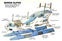
This picture shows a design drawing of the SEMAN and some of its components. The outrigger stabilizer and sails are not shown (see below) to make the design features more visible. Note that the intent of the SEMAN design is to maximize efficiency of movement and energy harvest and to provide space for growing food. In addition, the SEMAN should be stable for waves up to 6 feet and be able to right itself if turned on its side. Finally, the SEMAN is constructed in eight sections, so each section can be transported by road to the seashore for launch.
Complex Model-Static and Dynamic Stability
Tests showed that this model would be statically stable with scaled six-foot waves. Tests also showed that this model would be dynamically stable with scaled six-foot waves. Note, however, that if the model were pushed on its side, it would not right itself. A righting capability requires an outrigger and float for this dual hull design as will be shown later.
Upper Hull-Internal Structure

This picture shows the internal rib structure and internal skins of the upper hull. The upper hull is on its side.
Lower Front Hull-Internal Structure

This photo shows the internal structure and some skin on the lower front hull. Kirsten, is standing by the hull to give scale. She is six feet tall.
Lower Rear Hull with Outer Skin

This picture shows the lower rear hull partially skinned with 1/4 inch plywood, a fiberglass cover and a prime coat. The hull is upside down. Note an inner and an outer hull for flotation if the outer hull is punctured. There are separate compartments for flotation even if the inner hull is punctured. The hull is shown upside down. It is righted later in the construction process.
Completing the Upper Front Hull
This picture shows the upper front hull complete and ready for assembly.
Completing the Lower Front Hull

This picture shows the lower front hull skinned and ready for assembly. Note that the strut that connects the upper hull with the lower hull is attached. the lower front hull is now right side up.
Completing the Lower Rear Hull

This picture shows the lower rear hull complete and ready for assembly. Note that the two moveable rudder structures (not skinned) are also shown in this picture along with some cross structural members.
Lower Rear Hull and Outrigger-Ready for Assembly

This picture shows the lower rear hull complete and ready for assembly. Note a wing and an outrigger tube mount on the side. This assembly plus the outrigger flotation tube (not shown) allows the SEMAN to right itself even if the hull is pushed on its side. In addition, the wing and the outrigger assembly along with its flotation tube allow the SEMAN to gather energy from waves, by harnessing the tube motion with respect to the outrigger and main body of the SEMAN, which is stable. The lateral control surface is also shown in the forground.
[/private]
Lower Left Connection Fl ange
ange
This flange is the connection flange between the two sections of the lower hull. There is a matching flange on the lower rear hull. These two flanges will be glued and bolted together when the lower hull is ready for assembly.